
CNC Machining DFM: A Practical Design for Manufacturing Guide for Engineers
You designed a part. It looks great in CAD. Then the CNC shop calls and says the internal corner radius is too tight, the wall is too thin, and the threaded hole depth exceeds standard tap length. Sound familiar? This is why CNC machining DFM (Design for Manufacturing) matters — it's the difference between a part that machines smoothly and one that burns through your budget.
I've reviewed thousands of drawings over the years. The same mistakes show up again and again — sharp internal corners where end mills can't reach, deep narrow pockets that chatter, tight tolerances called out on features that don't need them. Here's what I tell every engineer who asks me how to design for CNC.
Internal Corner Radii: The #1 DFM Mistake
CNC end mills are round. That means every internal vertical corner will have a radius equal to the tool's radius. If your design calls for a sharp 90° internal corner, the machinist has to either EDM it or hand-finish it — both expensive options.
Rule of thumb: Design internal corner radii at least 1-2mm. Use the same radius across all internal corners so the machinist can use one tool for all of them. If you need a sharp corner in one area, specify it clearly and expect extra cost.
Here's the thing most designers don't think about — corner radius also determines tool diameter. A 3mm corner radius means a 6mm end mill. A 1mm radius means a 2mm end mill, which is slower, more fragile, and more expensive per part. Bigger tools cut faster. Let your machinist use a 12mm end mill instead of a 3mm one and you'll see the per-part price drop noticeably.
Wall Thickness and Feature Depth
Thin walls vibrate during machining. Vibration means poor surface finish, dimensional variation, and potential tool breakage. For aluminum, keep walls above 0.5mm. For steel, above 0.8mm. For plastics, above 1.0mm.
Deep narrow features are another problem. A slot that's 10mm wide and 100mm deep requires a long-reach tool — which deflects. The rule: depth should not exceed 4-6 times the tool diameter for standard machining. Beyond that, you're into specialized tooling territory.
Tolerance — Don't Over-Specify
I covered this in detail before, but for DFM specifically: every tight tolerance adds cost. The machine has to run slower, the tool has to be newer, and the inspection takes longer. A ±0.1mm tolerance on a non-critical face costs nothing. A ±0.01mm tolerance on the same feature can double the machining time.
DFM approach: Use loose block tolerances (±0.1mm or ±0.2mm) on the title block. Call out tight tolerances only on features that actually need them — press-fit bores, bearing seats, mating surfaces. Use GD&T symbols to specify what truly matters (true position, parallelism, runout) rather than tight block tolerance everywhere.
Threads and Tapped Holes
Blind tapped holes are a common source of DFM problems. Standard thread depth for a blind hole is 2x diameter for steel, 2.5x for aluminum. Deeper than that and you risk tap breakage — and a broken tap in a $200 part is a scrap part.
For M6 threads in aluminum, standard tap drill depth is about 18mm max with a 12mm full thread depth. If you need deeper threads, specify thread milling (stronger, more expensive) or use a larger thread size.
Thread relief: If a threaded hole intersects a cross-hole or internal cavity, add a thread relief — a small counterbore at the bottom of the thread. Without it, the last few threads may be incomplete or burred.
Material Selection for DFM
Aluminum 6061 is the most DFM-friendly material. Great machinability, good strength, low cost. If your part can be made from 6061, it probably should be.
Steel 1018 or 12L14 are the easiest steels to machine. 4140 is fine in annealed state. Stainless 304 is workable but expect slower speeds and shorter tool life.
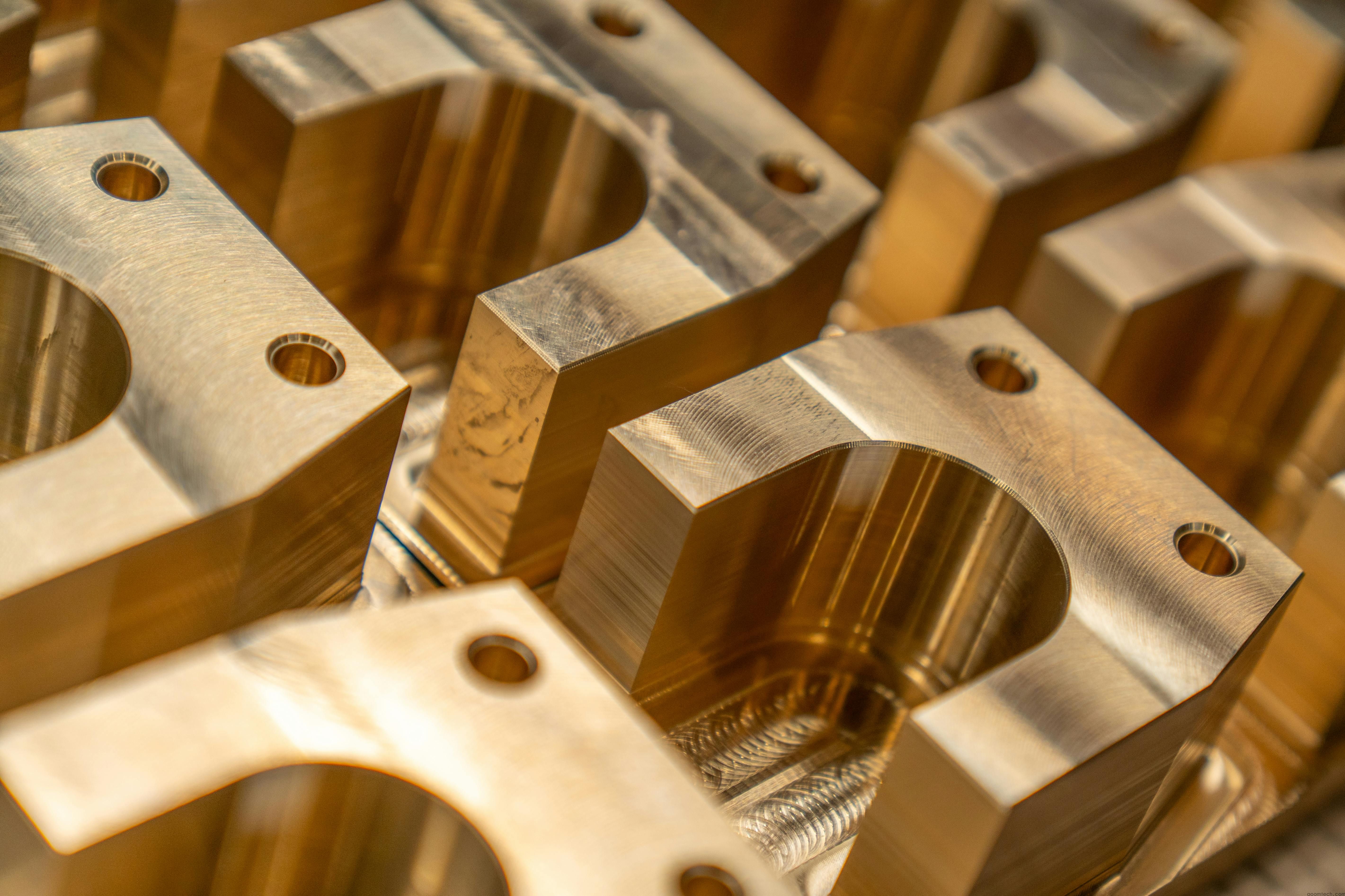
Brass machines beautifully — almost like butter. Great for small precision components, fittings, and electrical parts. Cost is moderate.
Plastics — Delrin (POM) and Nylon machine well. PEEK is expensive but excellent for high-temp applications. Thin wall sections in plastic can distort from cutting heat, so plan for adequate cooling between passes.
Undercuts and Special Features
Undercuts (features that can't be reached with a straight tool path from the top) require special tooling or multiple setups. A simple T-slot or dovetail undercut can be done with a lollipop cutter or slitting saw. Complex undercuts may require 5-axis machining or EDM.
DFM check: Can all features be machined with standard tool orientations (top, bottom, 4 sides)? If yes, it's a simple 3-axis job. If you need angled holes, curved bottom surfaces, or undercuts, you're looking at 5-axis or multi-setup costs.
DFM Checklist — Before You Send the Drawing
- Internal corner radii ≥ 2mm (preferably matching radius throughout)
- Wall thickness ≥ 0.5mm (Al), 0.8mm (steel), 1.0mm (plastic)
- Pocket depth ≤ 4x tool diameter
- Thread depth ≤ 2.5x diameter (blind holes)
- Generous radii on external corners too (reduces stress risers)
- Avoid sharp internal corners (add radius or specify EDM)
- Use block tolerance for non-critical dimensions
- GD&T callouts only where mating or function demands it
- Add chamfers to threaded hole entries (eases tapping)
- Specify surface finish with Ra values, not vague notes
- Include stock material size and condition (e.g., 6061-T651 plate)
- Flag any features that might need secondary operations (deburring, tumbling)
My Take — The Best DFM Advice I Can Give
Send your print to the machinist before finalizing it. A 10-minute DFM review by someone who actually runs the machine will catch 90% of the costly mistakes. We do this for free at AOOM Technology — send us your drawing, we'll mark it up with DFM suggestions, and you'll get a better part at a lower price.
AOOM Technology has been providing CNC machining DFM reviews for engineers across automotive, medical, aerospace, and industrial sectors. We know what works and what doesn't. If you're designing a part for CNC machining, get in touch early. A quick DFM review before you lock the design saves time, money, and a lot of phone calls. Contact AOOM today.
 CNC Machining DFM: A Practical
 CNC Machining Finishing Option
 CNC Prototyping for Product De