


Precision CNC Machining Precautions for Large Copper Parts
Precision CNC Machining Precautions for Large Copper Parts
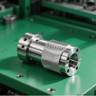
Precision CNC Machining Precautions for Large Copper Parts is a critical topic in modern manufacturing, especially in industries such as power systems, heat exchangers, electronics, and heavy industrial equipment. Large copper components are widely used because copper has excellent thermal and electrical conductivity. However, copper is also soft, sticky during cutting, and easily deformed, which makes precision machining more challenging—especially when the part size is large.
To achieve stable quality and tight tolerances, manufacturers must carefully control machines, tools, processes, and inspection methods. This article explains practical machine-related precautions in large copper part CNC machining, part handling, tooling strategies, machining parameters, and quality control methods based on real-world CNC machining practices.
Machine-Related Precautions
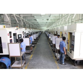
Machine Capacity and Rigidity
When machining large copper parts with high precision, the CNC machine must have sufficient working capacity. The work envelope should fully accommodate the size of the copper component without forcing repositioning during machining. If the machine is too small, repeated setups will introduce alignment errors and reduce dimensional accuracy.
Rigidity is equally important. Large copper parts often require long cutting passes, and even small vibrations can cause surface waviness or dimensional deviation. A rigid machine structure—such as a heavy cast-iron frame, reinforced column design, and high-quality linear guides—helps maintain stability during cutting.
For example, in the production of large copper heat exchanger plates, any vibration during milling can cause uneven sealing surfaces, which directly affects thermal performance and leakage resistance.
How to assess machine capacity and rigidity:
Check maximum table load and work envelope dimensions
Evaluate spindle-to-table distance stability under load
Look for machine structure material (cast iron or mineral casting is preferred)
Review manufacturer specifications for vibration damping and stiffness ratings
Spindle Performance
Spindle performance plays a major role in precision CNC machining precautions for large copper parts. Copper is a soft and ductile material, so it requires a stable spindle rather than extremely aggressive cutting power.
A well-balanced spindle ensures smooth cutting and prevents chatter marks on the surface. High-speed capability is useful for finishing operations, while stable torque is required for rough machining of thick copper blocks.
If spindle power is too low, the tool may struggle during deeper cuts, leading to inconsistent chip formation and poor surface finish. On the other hand, excessive spindle vibration can cause tool chatter, especially when machining large flat copper surfaces.
Part-Handling Precautions
Fixturing and Clamping
Copper is a relatively soft and malleable metal, which means improper clamping can easily cause deformation. Therefore, fixturing design is a key factor in maintaining accuracy.
Proper fixtures must distribute clamping force evenly across the workpiece. Localized pressure can leave permanent marks or distort flatness, especially in large thin copper plates.
Common solutions include:
Soft-jaw chucks to reduce surface damage
Custom fixtures with multiple support points
Vacuum fixtures for flat copper sheets
Support plates to prevent bending under cutting forces
In complex geometries, modular fixtures are often used to adapt to different copper part shapes while maintaining stability.
Loading and Unloading
Large copper parts can be heavy and difficult to handle safely. Careless movement can result in scratches, dents, or even dimensional distortion before machining begins.
Use proper lifting equipment such as cranes, hoists, or vacuum lifters depending on part geometry and weight. During loading, ensure the part is aligned correctly with fixture reference points to avoid setup errors.
During unloading, protective padding should be used to prevent surface damage. Operators should avoid dragging copper parts across hard surfaces, as copper scratches easily.
Cutting-Tool Precautions
Tool Selection
Tool selection is a major factor in cutting-tool precautions for large copper part precision machining. Because copper tends to stick to cutting tools, tool geometry and coating must be carefully chosen.
Carbide tools are commonly used due to their hardness and wear resistance. Tools with a sharp cutting edge and positive rake angle help reduce cutting resistance and improve chip evacuation.
Recommended tool types include:
Carbide end mills with polished flutes for better chip flow
Single or two-flute cutters to reduce chip congestion
Tools with anti-adhesion coatings (such as TiB2 or DLC coatings)
Tool Wear and Replacement
Tool wear directly affects machining accuracy, especially in long production runs of large copper parts. A worn tool can cause dimensional drift, poor surface finish, and increased cutting temperature.
Operators should regularly inspect tools for:
Edge dulling or rounding
Built-up edge (copper adhesion on tool surface)
Uneven wear patterns
As a general guideline, tools should be replaced based on machining time, number of cycles, or visible wear indicators rather than waiting for complete failure. Preventive replacement ensures consistent precision.
Machining-Process Precautions
Cutting Parameters
Optimizing cutting parameters is essential for stable precision CNC machining precautions for large copper parts. Copper has high thermal conductivity, but it still generates heat at the cutting zone, which can affect dimensional stability.
Key parameter considerations include:
Cutting speed: Typically moderate to high, depending on alloy (e.g., 80–250 m/min as a general industrial range)
Feed rate: Must be balanced to avoid tool rubbing or excessive force
Depth of cut: Should be controlled to avoid deformation in large thin sections
Excessively high cutting speed may increase heat and cause thermal expansion, while too low speed may lead to built-up edge formation. A balanced approach is necessary based on copper grade and part geometry.
Chip Management
Copper produces continuous, ductile chips that can easily wrap around tools or accumulate on the workpiece. Poor chip control can damage surface quality and increase tool wear.
Effective chip management methods include:
High-pressure coolant systems to break and flush chips
Flood coolant to reduce heat and prevent sticking
Chip conveyors for large-volume machining operations
Air blow systems for finishing passes
Proper chip evacuation is especially important in deep cavity machining of large copper parts.
Quality-Control Precautions
In-Process Inspection
In-process inspection is essential for maintaining accuracy during large copper part machining. Since copper can deform under heat and force, continuous monitoring helps detect problems early.
Common inspection methods include:
Calipers and micrometers for dimensional checks
Dial indicators for flatness and runout measurement
Coordinate Measuring Machines (CMM) for high-precision geometry verification
Typical inspection points include flatness of large surfaces, hole position accuracy, and thickness consistency in structural copper parts.
Final Inspection and Documentation
After machining is complete, a full inspection ensures the part meets all design specifications. This step is essential for industries that require strict compliance, such as electrical systems and thermal equipment manufacturing.
Final inspection should include:
Dimensional accuracy checks against CAD drawings
Surface roughness evaluation
Visual inspection for scratches, dents, or tool marks
All results should be recorded in detailed documentation, including measurement data, inspection tools used, operator information, and any deviations found. This supports traceability and aligns with ISO-quality management practices commonly used in CNC manufacturing.
Conclusion
Successfully applying Precision CNC Machining Precautions for Large Copper Parts requires careful attention to every stage of production—from machine selection and fixture design to tool management, cutting optimization, and strict quality control.
By following structured machining practices and applying proven industrial methods, manufacturers can reduce deformation, improve surface quality, and achieve consistent precision even in large-scale copper components. This is essential for ensuring reliable performance in demanding applications such as heat exchangers, electrical conductors, and industrial systems.
 How to Ensure Precision in CNC
 Small Batch Precision CNC Mach
 What surface finish can CNC ma
 CNC Machining Tolerance Settin