

5 Tips for Precision Control in CNC Machining of Aerospace Parts
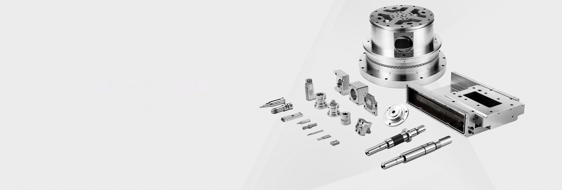
In aerospace manufacturing, precision is not optional—it is a strict requirement for safety and performance. CNC machining is widely used to produce critical aerospace components such as turbine blades, engine mounts, landing gear parts, and structural brackets. These parts must perform reliably under extreme pressure, heat, and vibration. Even a very small dimensional error can lead to serious performance problems or safety risks.
This article explains 5 Tips for Precision Control in CNC Machining of Aerospace Parts and provides practical methods to improve accuracy, stability, and quality in real production environments.
Importance of Precision in Aerospace CNC Machining
Aerospace components operate in highly demanding conditions, including high-speed rotation, extreme temperature changes, and continuous mechanical stress. Because of this, tolerance levels are extremely tight.
For example, a turbine blade with a slight dimensional deviation can cause imbalance in the engine, leading to vibration, reduced efficiency, or even catastrophic failure. Similarly, an improperly machined engine mount may not distribute loads correctly, affecting the structural safety of the aircraft.
This is why aerospace manufacturing follows strict standards such as AS9100 quality systems and requires strong precision control in CNC machining of aerospace parts at every stage.
Tip 1: Optimize Part Design for Machining
Consider Machinability in Design
Good precision starts with good design. Engineers should consider machinability during the design phase. Complex shapes should be simplified when possible to reduce machining difficulty and improve accuracy.
For example, avoiding sharp internal corners can prevent tool stress and breakage. Using standard hole sizes, standard radii, and practical tolerances also improves manufacturability.
A key practice is collaboration between design engineers and machinists to improve part design for precision in aerospace CNC machining without affecting functional requirements.
Use CAD/CAM Software Effectively
Modern CAD/CAM systems play a key role in precision manufacturing. CAD (Computer-Aided Design) ensures accurate 3D modeling, while CAM (Computer-Aided Manufacturing) generates optimized toolpaths for CNC machines.
Simulation tools inside CAM software help detect collisions, toolpath errors, or inefficient cutting strategies before actual machining begins. This reduces trial-and-error and improves consistency.
For aerospace parts, using simulation and digital verification is essential to achieve high precision and reduce production risk.
Tip 2: Select the Right Materials and Tools
Material Selection
Material choice directly affects machining accuracy. Aerospace components often use materials like titanium alloys, aluminum-lithium alloys, and high-strength steels due to their strength-to-weight ratio and heat resistance.
However, these materials behave differently during machining. Titanium, for example, generates more heat and causes faster tool wear, while aluminum alloys are easier to machine but may deform if not properly controlled.
Selecting the right material based on performance requirements and machining conditions is essential for maintaining dimensional stability.
Tool Selection and Maintenance
High-quality cutting tools are critical for precision. Carbide tools are commonly used in aerospace machining due to their hardness and wear resistance.
To maintain accuracy, tools must be regularly inspected for wear, chipping, or coating damage. Dull tools can cause vibration, poor surface finish, and dimensional errors.
A structured maintenance schedule improves consistency and supports tool selection for precision in aerospace part machining.
Tip 3: Optimize CNC Machining Parameters
Spindle Speed, Feed Rate, and Depth of Cut
Machining parameters strongly influence precision outcomes. Spindle speed, feed rate, and depth of cut must be carefully balanced based on material type and part geometry.
If spindle speed or feed rate is too high, excessive heat may occur, leading to thermal expansion and dimensional inaccuracy. If too low, tool rubbing may occur, reducing surface quality.
Proper parameter selection ensures stable cutting conditions and consistent accuracy. Engineers often use machining databases and real-time testing to determine optimal settings for aerospace parts.
Use of Coolants and Lubricants
Coolants and lubricants help control heat and friction during machining. Coolants reduce thermal deformation, while lubricants improve surface finish and extend tool life.
For aerospace materials, water-soluble coolants are often used for aluminum, while specialized oil-based or high-pressure cooling systems may be required for titanium alloys.
Proper coolant selection supports stable machining conditions and improves overall precision control.
Tip 4: Implement Rigorous Quality Control Measures
In-Process Inspection
Quality control should not wait until the end of production. In-process inspection ensures errors are detected early.
Tools such as Coordinate Measuring Machines (CMM), optical comparators, and surface profilometers are used to check dimensions, alignment, and surface quality during machining.
For example, checking hole diameter or flatness during production helps prevent large batches of defective aerospace parts.
Final Inspection and Testing
After machining, aerospace components must undergo strict final inspection. This includes dimensional verification, surface roughness testing, and non-destructive testing (NDT).
Methods such as ultrasonic testing, X-ray inspection, and magnetic particle inspection are used to detect internal cracks or hidden defects.
Functional testing may also simulate real operating conditions such as high-speed rotation or extreme temperature exposure to ensure reliability.
This stage is critical in quality control for precision in aerospace CNC machining and ensures compliance with aerospace safety standards.
Tip 5: Train and Empower the Machining Team
Technical Training
Even with advanced machines, human expertise remains essential. Operators and programmers must understand CNC systems, aerospace requirements, and material behavior.
Training in multi-axis machining, advanced toolpath programming, and CAD/CAM software improves production accuracy and reduces errors.
A skilled workforce ensures better decision-making during machining operations and supports long-term precision stability.
Continuous Improvement and Feedback
Precision control is not a one-time task. Continuous improvement is necessary for long-term success.
Teams should regularly review machining results, tool performance, and inspection data to identify improvement opportunities. Feedback from operators can help optimize setups, reduce tool wear, and improve cycle times.
This continuous learning approach strengthens overall manufacturing quality and supports consistent aerospace-grade precision.

Conclusion
Achieving high accuracy in aerospace manufacturing requires a combination of smart design, correct material and tool selection, optimized machining parameters, strict quality control, and a skilled workforce.
By applying these 5 Tips for Precision Control in CNC Machining of Aerospace Parts, manufacturers can significantly improve reliability, reduce defects, and meet strict aerospace industry standards.
In a field where safety and performance are critical, precision is not just a goal—it is a responsibility.
 Process of Custom High-Precisi
 CNC Machining Parameter Settin
 5 Key Tips for CNC Machining o
 Small-batch Precision Parts 5-