
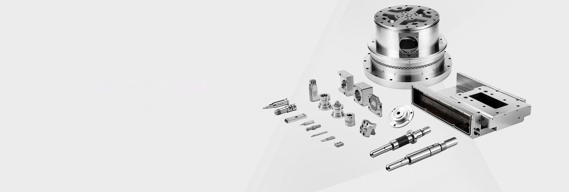
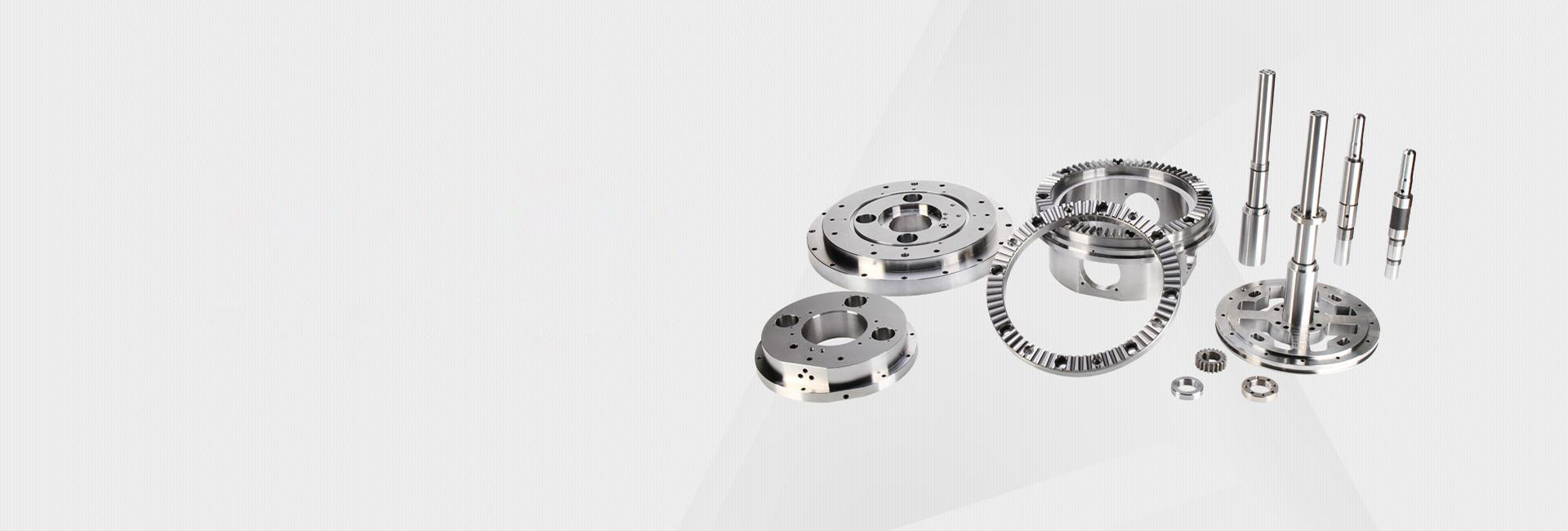
5 Key Control Techniques to Solve Deformation in CNC Machining of Aluminum Profiles
Why Aluminum Profile Machining Deforms
Aluminum profiles are tricky. They're light, thermally conductive, and machine well—until they don't. I've spent years dealing with deformation on long extrusions and thin-walled sections. The problem is consistent: the part warps, twists, or bows during or after machining.
Here's what causes it. Aluminum has low elastic modulus. That means it deflects easily under cutting forces. It also conducts heat fast, so localized heating during machining causes expansion. And on top of that, the extrusion process leaves residual stresses in the profile that release when you remove material.
Technique 1: Material Pretreatment
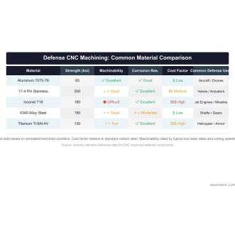
I start by selecting the right alloy. 6061 machines easier than 7075, but 7075 has higher strength after machining. For most profile work, 6061-T6 is ideal. It's stable and cuts clean.
Stress relief annealing makes a big difference. We heat the profile to 300°C for two hours and cool slowly. This reduces internal stress by over 60%. I've run tests comparing annealed vs. non-annealed 6061 extrusions. The annealed parts show 80% less post-machining warp.
Technique 2: Layered Cutting Strategy
Never machine an aluminum profile to final dimensions in one pass. I separate rough and finish operations.
Rough machining removes most of the material but leaves 1-1.5mm of stock. This lets the part release its internal stresses during roughing. Finish machining then takes 0.2-0.3mm per pass to reach final dimensions. The light cuts produce minimal heat and cutting forces.
For long profiles, I segment the machining. Cut every 200mm along the length rather than one continuous pass. This reduces vibration from tool engagement and keeps the workpiece stable.
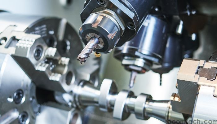
Technique 3: Tool Selection and Parameters
Sharp tools are non-negotiable for aluminum. Dull edges generate heat, and heat causes expansion and distortion.
I use diamond-coated end mills designed for aluminum. They stay sharp longer and have excellent chip evacuation. Parameter settings are critical:
Spindle speed: 12,000-18,000 RPM depending on tool diameter. High enough for clean cutting, but not so high that friction heat builds up.
Feed per tooth: 0.08-0.12mm. Too slow and the tool rubs instead of cutting. Too fast and cutting forces cause deflection.
Depth of cut: No more than 2mm for roughing, 0.5mm for finishing. Light cuts minimize cutting force and heat generation.
Critical rule: Replace tools when edge wear exceeds 0.1mm. I've seen operators try to squeeze one more run from a worn end mill. The heat spike nearly always causes distortion.
Technique 4: Smart Fixturing
Standard vises crush soft aluminum profiles. I use contoured soft jaws that match the profile shape. This distributes clamping pressure evenly and prevents local deformation.
For sheet and plate work, vacuum chucks are excellent. The hold is uniform across the entire surface. The minimum requirement is a surface finish of Ra 3.2 or better on the vacuum side.
For long extrusions, I add adjustable supports in the middle and at both ends. Gravity causes sag on unsupported spans over 300mm. A simple adjustable strut under the workpiece prevents this entirely.
Technique 5: Cooling That Works
Flood coolant isn't always the answer. Too much coolant causes thermal shock—the cold fluid hits a warm part and creates uneven contraction.
I prefer Minimum Quantity Lubrication (MQL). It sprays a fine mist of lubricant directly at the cutting interface. This controls temperature with minimal thermal impact on the rest of the part. It also prevents aluminum chips from welding to the tool.
For deep hole drilling, through-spindle coolant is necessary. The coolant goes directly to the cutting edge and flushes chips out. Without it, heat builds up fast and the hole location drifts.
Putting It All Together
These five techniques work together. Good material prep, layered cutting, sharp tooling, proper fixturing, and controlled cooling. Apply all five and you eliminate most deformation issues on aluminum profiles.
Send your CAD files to chen@aoomtech.com for a quote within 24 hours.
 CNC Machining for Defense and
 CNC Machining for Aerospace: M
CNC Machining for Medical Devi
CNC Machining for Aerospace: M
CNC Machining for Medical Devi
 CNC Precision Machining Parts: