
How to Ensure Drilling Precision in CNC Machining of Connecting Rods
In modern engine manufacturing, connecting rods play a critical role in transferring motion between the piston and crankshaft. One of the most important processes in producing high-quality connecting rods is drilling. Achieving high accuracy in this process is essential for performance, durability, and safety. This article explains How to Ensure Drilling Precision in CNC Machining of Connecting Rods using practical engineering methods, from preparation to final inspection.
Introduction to Drilling Precision in Connecting Rod CNC Machining
Importance of Drilling Precision
In CNC machining of connecting rods, drilling precision is extremely important because the drilled holes define the alignment and assembly of engine components. These holes are used for bolts, bushings, and bearing interfaces. Even a small deviation in hole position or diameter can lead to serious problems.
For example, if a bolt hole is drilled off-center, the connecting rod may not align properly with the crankshaft. This can cause uneven load distribution, increased vibration, abnormal wear, and in extreme cases, engine failure. Similarly, incorrect bore sizing can lead to loose or overly tight fits, reducing engine efficiency and lifespan.
Pre-drilling Considerations for Connecting Rod CNC Drilling
Part Design and Fixturing
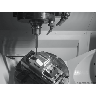
Good drilling precision starts with proper design. The geometry of the connecting rod should allow easy tool access and stable positioning. Designers should ensure that drilling areas are not blocked by complex surfaces and that reference faces are clearly defined.
Fixturing is equally important. A strong and stable fixture prevents movement during drilling, which is one of the main causes of inaccuracy. Common fixture methods include:
Hydraulic or mechanical clamps for high clamping force
Custom precision jigs designed for repeatability
Magnetic fixtures (for compatible materials)
To ensure alignment, the fixture must match the CNC machine coordinate system precisely. Using locating pins and datum surfaces helps maintain consistency. This is a key part of pre-drilling considerations for connecting rod CNC drilling.
Material Analysis
Different connecting rod materials such as alloy steel, forged steel, or aluminum alloys behave differently during drilling. Understanding material properties is essential for selecting the correct tools and parameters.
Hard materials like forged steel require high-strength carbide drills and lower cutting speeds. Softer materials like aluminum alloys are easier to machine but can cause burrs or hole enlargement if feed control is poor.
Key material factors include:
Hardness – affects tool wear and cutting force
Ductility – influences chip formation
Thermal conductivity – affects heat buildup during drilling
A proper material analysis helps optimize machining strategy and avoid common defects such as tool breakage or hole deformation.
Drill Bit Selection and Maintenance
Appropriate Drill Bit Choice
Choosing the correct drill bit is essential for achieving high accuracy. In connecting rod machining, drill selection depends on hole size, depth, and material type.
Important factors include:
Drill diameter: Must match design specifications exactly
Point angle: Typically 118° or 140° for better centering in tough materials
Flute design: Parabolic flutes improve chip evacuation in deep holes
For deep-hole drilling, coated carbide drills are often preferred due to their strength and wear resistance. This process is known as drill bit selection in connecting rod drilling precision.
Drill Bit Maintenance
Even the best drill bit loses performance over time. Regular maintenance ensures consistent accuracy and surface quality.
Signs of drill wear include:
Increase in hole diameter variation
Burn marks or rough hole surfaces
Higher cutting force or vibration
Maintenance practices include sharpening, coating inspection, and timely replacement. Proper lubrication and cooling also extend tool life and reduce heat damage. A well-maintained tool directly improves drilling stability and accuracy.
CNC Machining Parameters Optimization
Spindle Speed and Feed Rate
Spindle speed and feed rate are key parameters that control drilling performance. Incorrect settings can lead to tool wear, poor surface finish, or inaccurate holes.
General guidelines include:
Hard materials: lower speed, moderate feed
Soft materials: higher speed, controlled feed
Small diameter drills: higher speed, lower feed per revolution
Too high spindle speed may cause overheating, while too low feed rate can lead to rubbing instead of cutting. Balancing these factors is essential for stable machining.
Depth of Cut and Peck Drilling
For deep holes in connecting rods, chip evacuation becomes critical. Poor chip removal can cause tool deflection and hole deviation.
Peck drilling is commonly used to solve this issue. In this method, the drill periodically retracts to break and remove chips. This reduces heat buildup and improves hole accuracy.
Proper control of depth of cut prevents overload on the drill bit and ensures consistent cutting performance throughout the operation.
Quality Control in CNC Machining of Connecting Rod Holes
In-process Inspection
Real-time inspection is a key step in ensuring accuracy during production. Measuring tools such as calipers, micrometers, and bore gauges are used to verify hole size and position.
Advanced systems like laser alignment tools can also check tool positioning and perpendicularity before and during drilling.
Benefits of in-process inspection include:
Early detection of dimensional errors
Reduced scrap rate
Immediate process adjustment capability
This is an essential part of quality control in CNC machining of connecting rod holes.
Final Inspection and Corrective Actions
After machining, a full inspection ensures that all drilled holes meet design specifications. This includes checking diameter, position accuracy, roundness, and surface finish.
If issues are found, corrective actions may include:
Reaming to correct hole size
Re-drilling if deviation is minor and recoverable
Scrapping parts with severe dimensional errors
Final inspection ensures that only fully compliant connecting rods are assembled into engines, maintaining safety and performance standards.
Conclusion
Achieving high drilling precision in connecting rod manufacturing requires a complete system approach. From design and fixturing to tool selection, machining parameters, and quality control, every step influences final accuracy.
By carefully applying engineering principles and maintaining strict process control, manufacturers can significantly improve reliability and reduce defects. Understanding How to Ensure Drilling Precision in CNC Machining of Connecting Rods is essential for producing high-performance engine components that meet modern automotive standards.
Consistent attention to detail, combined with advanced CNC technology, ensures long-term stability, efficiency, and product quality in precision machining operations.
 Process of Custom High-Precisi
 CNC Machining Parameter Settin
 5 Key Tips for CNC Machining o
 Small-batch Precision Parts 5-