
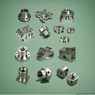
CNC Machining Process for Precision Robot Parts
Industrial robots need parts built to very tight dimensions. A small error in a robot joint or sensor mount can make the whole machine fail. For this reason, engineers use CNC machining — which means computer-controlled cutting tools — to make robot parts. This CNC machining process for precision robot parts removes material from a solid block to create exact shapes. By following precise instructions, CNC machines can hold very small tolerances, often in the range of hundredths of a millimeter. In practice, even 0.001 inches (0.025 mm) of misalignment in a robot component can cause noticeable errors. We explain here how to meet the precision requirements, choose the right materials, use proper tooling, and ensure quality in CNC machining for robotics.
Precision Levels in CNC Machining Robot Parts
Robot parts usually demand very high accuracy. Typical precision levels are on the order of 0.01 mm or better. For example, critical holes or bores in a robot arm can be held to ±0.005–0.010 mm. Flat mounting faces or bearing surfaces are often machined to within ±0.005–0.015 mm. Larger or less-critical features may use tolerances of ±0.02–0.05 mm. All these tight tolerances help ensure the robot moves smoothly and repeatably. Even small deviations can add up: a 0.001 inch error in an encoder mount can throw off the robot’s position readings. To reach these levels, machine shops use very stable CNC equipment and careful setup. They often include on-machine probing to check and correct datum alignment before the final cuts. In short, expect precision levels on the order of a few microns (0.001 mm) for the most critical features.
Material Options for CNC-Machined Precision Robot Components
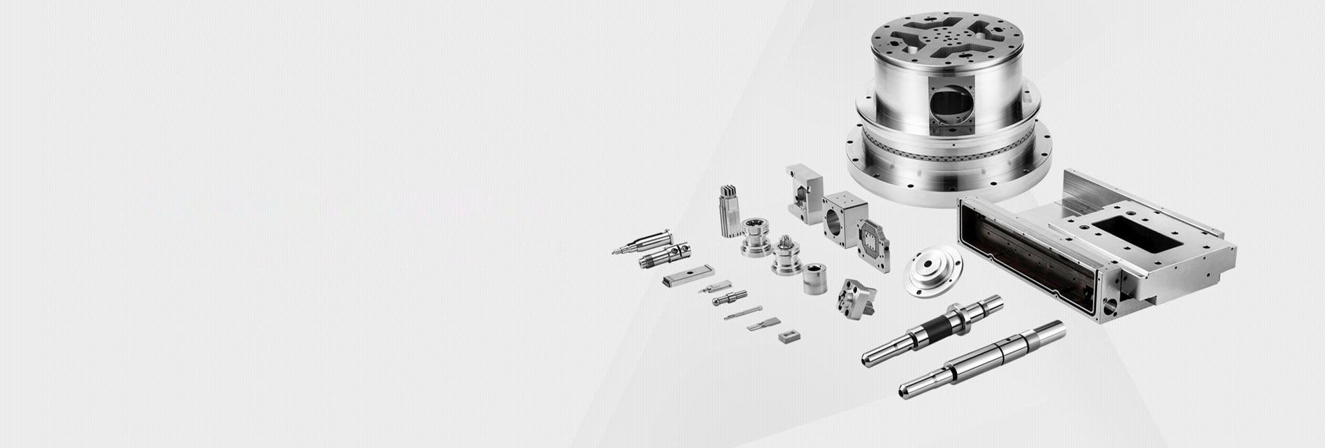
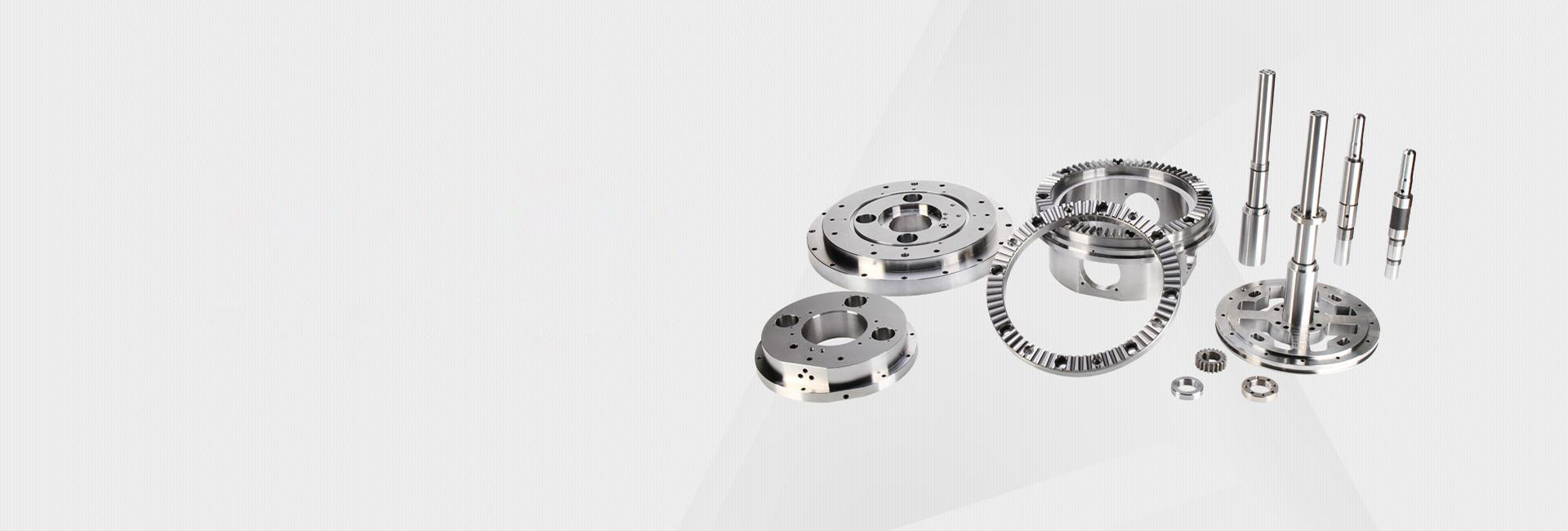
The choice of material affects weight, strength, and machining ease. Common materials for CNC-machined precision robot components include aluminum alloys, steels, titanium, and engineering plastics. Aluminum 6061-T6 is often the first choice for robotic frames and housings. It is light, strong (310 MPa tensile strength), and machines quickly. For parts that see higher stress, aluminum 7075-T6 (572 MPa strength) is used, though it is a bit harder to cut. Stainless steels like 304 or 316L give extra strength and corrosion resistance for heavy-duty or medical robots. For the lightest yet strongest parts, titanium alloy (Ti-6Al-4V) is an option, especially in aerospace or medical robots. Plastics like PEEK or Delrin are used for non-structural parts, such as sensors or cable guides, where weight savings and chemical resistance matter. In summary, a wide range of materials is used, and all can be machined to tight specs. Table of typical choices:
Aluminum 6061-T6: Lightweight, easy to machine, used for frames and plates.
Aluminum 7075-T6: Stronger for high-load parts like gripper fingers.
Stainless Steel 304/316L: Heavy but corrosion-resistant, for surgical or food robots.
Titanium Ti-6Al-4V: Very high strength-to-weight, for aerospace-quality robots.
Plastics (PEEK, Delrin): Light, non-conductive, for bearings, guides, or housings.
The best material depends on the robot’s needs for strength, stiffness, and weight. Many designers start with 6061 aluminum (it’s inexpensive and easy to cut) and switch to 7075 or steel if more strength is required.
Tooling and Machining Strategies
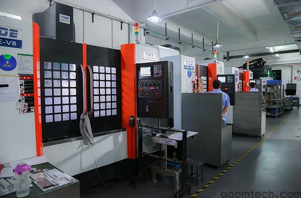
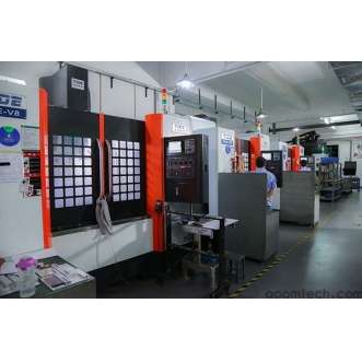
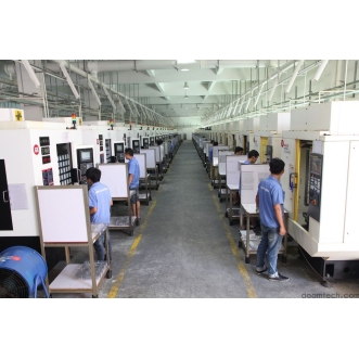
Choosing the right tools and processes is key to meeting precision needs. Modern robot parts often have complex shapes, so shops use multi-axis machines. A 5-axis CNC machine, which can tilt and rotate the part, can cut angled holes and curved surfaces in one setup. This avoids repositioning the part multiple times, which can introduce alignment errors. Using one setup helps keep axes and bores aligned within tight tolerances. For simpler shapes like flat plates or brackets, a 3-axis CNC mill may be enough, but more fixturing is needed.
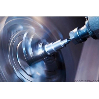
Specialty cutting tools are also important. For precision holes (bores), machinists use single-point boring bars or reamers that can achieve ±0.005 mm accuracy. For threads, they use CNC taps or thread mills to get precise fits. For flat surfaces, high-feed face mills are chosen for uniform finish. Very small cutting tools or special micro-tools may be used for fine details. All tools should be as short and stiff as possible. Shops often use shrink-fit tool holders or precision collets to minimize tool vibration (runout under 0.003 mm). This keeps the cutting tip stable and accurate. Carbide tools with wear-resistant coatings (like TiAlN) are common to keep cutting edges sharp when machining hard metals.
CNC operators also control cutting conditions carefully. They may use climb-milling (cutting direction that pulls the tool into the workpiece) to reduce side force, especially on thin walls. For very thin sections, they might add temporary supports (like machinable wax) to prevent the wall from bending under the cutter. Radial depth of cut is kept small (for example, under 0.15 mm on finish passes) to limit vibration and deflection. Coolant is used to flush chips and cool the part; in fact, high-pressure through-tool coolant (e.g. 60 bar) is used on aluminum to reduce heating and expansion. Sometimes the tightest features are cut at the end of the operation cycle, after the part has cooled down to reduce size changes from heat.
Overall, careful selection of machine type, tool paths, and cutting parameters is needed to optimize CNC machining for precision robot parts. The goal is to remove material efficiently while keeping each feature within its tolerance. Using advanced strategies (like on-machine probing for alignment, zero-point clamping to repeatable locations, and constant tool monitoring) helps achieve consistent quality.

Quality Control in CNC Machining of Precision Robot Parts
After machining, every part must be checked against its specifications. Quality control in CNC machining of precision robot parts is strict. Typically, parts go through a staged inspection:
Initial dimensional check with hand tools (calipers, micrometers) to ensure nothing is way off before CMM inspection.
Full CMM (Coordinate Measuring Machine) inspection using a probe to measure all critical dimensions against the design. Modern CMMs can automatically scan holes, slots, and surfaces to a few microns of accuracy.
Surface roughness measurement, since very smooth finishes (low friction) are important for robot bearings and moving parts.
Go/no-go gauges or pin gauges for hole fits (to test if shafts or bearings will fit properly).
Visual inspection under magnification to catch burrs, scratches, or chips.
Documentation review (material certificates, such as ASTM B209 for aluminum, to confirm alloy and hardness).
These steps help catch any errors before parts are shipped. The shop will provide a certificate of conformance and often a First Article Inspection report showing all measured values. Good manufacturers follow an ISO 9001–based quality system so that each batch of parts is traceable and meets customer requirements. By inspecting on high-precision machines and following standard procedures, shops can guarantee that robot parts fit together in assembly and perform reliably.
In summary, making precision robot parts by CNC machining involves knowing the required tolerance, picking materials that balance weight and strength, using the right tools and machines, and thoroughly checking the result. With these practices, CNC machining delivers the precise, durable components needed for modern industrial robots.
 How to Ensure Precision in CNC
 Small Batch Precision CNC Mach
 What surface finish can CNC ma
 CNC Machining Tolerance Settin