
Guide to 5-Axis CNC Machining of Complex Parts
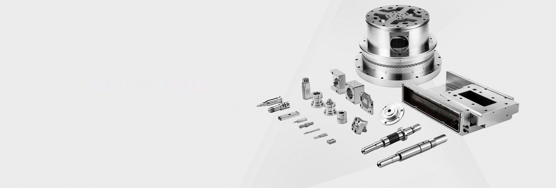
5-axis machining is used when a part is too complex for normal 3-axis work, or when too many re-clamps would create error, delay, and extra cost. In simple terms, a 5-axis machine uses the three standard linear axes and adds two rotary axes, so the tool can approach the job from many angles. This makes it possible to machine deep cavities, curved surfaces, undercuts, and multi-sided features in one setup or in far fewer setups than a standard machine.
This Guide to 5 - Axis CNC Machining of Complex Parts focuses on the problems people actually face on the shop floor: when 5-axis is worth using, how to program it without making it harder than it should be, how to choose tools that stay stable, and how to avoid setup mistakes that lead to scrap. The goal is simple: help you machine difficult parts with better accuracy, better surface finish, and fewer surprises.
Why 5-axis machining matters for complex parts
The biggest gain in 5-axis work is not just “more movement.” The real gain is fewer setups. When a part is moved from fixture to fixture, every new setup adds time and creates another chance for location error. Autodesk states that multi-axis machining can machine an entire part in a single setup, which reduces setup-related errors. Haas and Hurco make the same point from a machine tool view: cutting more sides in one clamping helps reduce setup time and increase accuracy on complex parts.
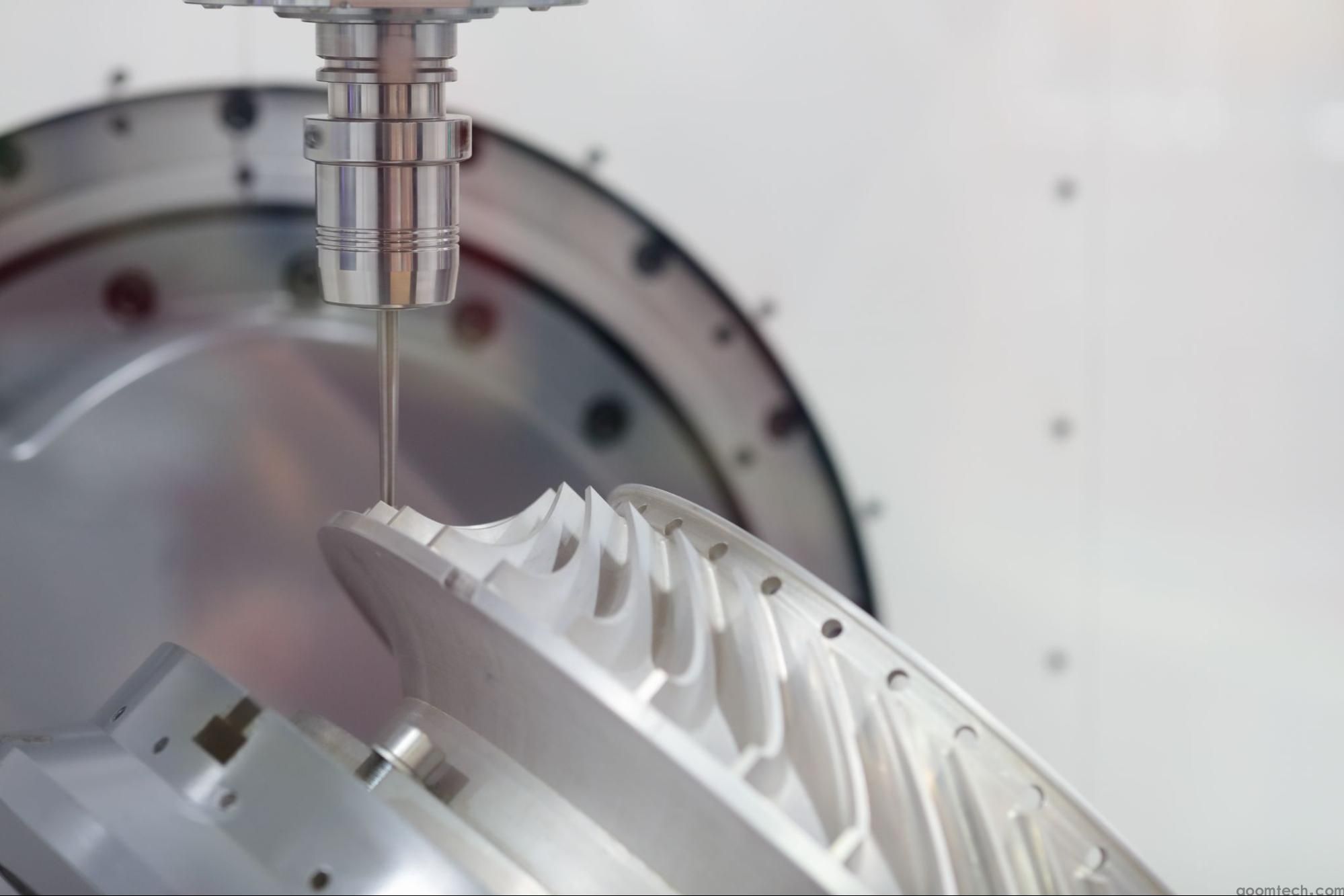
Another major benefit is tool position. Because the part or tool can tilt, the cutter can often stay shorter and more rigid. Autodesk notes that shorter cutting tools are less likely to deflect, which helps surface finish. Haas also recommends using the shortest tools possible on 5-axis jobs, and its chatter guide explains that shorter tools are more stable than longer ones. This is one of the core advantages of 5 - axis CNC machining for complex components: better access without depending on long, flexible tools.
For finish quality, 5-axis can also reduce hand work. Sandvik Coromant says finishing on a 4- or 5-axis machine with the right software and programming techniques can reduce or even remove manual completion work, while improving geometry and surface quality. That matters on molds, turbine parts, medical parts, and other components where polishing or blending can cost many hours.
Choosing between 3+2 and full simultaneous 5-axis
Many shops make 5-axis harder than it needs to be by jumping straight to full simultaneous motion. In real production, that is often the wrong first move. Autodesk explains the difference clearly: in simultaneous 5-axis, all five axes move together, which is ideal for smoothly following complex surfaces. In 3+2 machining, the rotary axes move to an angle, lock in place, and then the machine cuts like a 3-axis machine. Autodesk describes 3+2 as a good fit for angled holes and multi-side features, with simpler programming and fewer setups.
A practical rule is this: use 3+2 when you need access at an angle, but the actual cut can still be done with stable 3-axis motion. Use simultaneous 5-axis when the tool angle must keep changing during the cut, such as on sculpted surfaces, impeller-style shapes, or hard-to-reach flowing geometry. Hurco also notes that 5-sided machining, or 3+2, is a strong transition path from 3-axis because it reduces setup time and increases accuracy without the full programming load of continuous 5-axis motion.
For many shops, the fastest route to success is to start with a mixed strategy. Rough simple features in 3-axis or 3+2. Drill and machine side features in 3+2. Reserve simultaneous 5-axis for finishing the surfaces that truly need continuous tool orientation. This approach lowers programming risk and usually makes prove-out easier. Autodesk’s guidance on 3+2 versus simultaneous machining supports exactly this kind of choice-by-feature approach.
A practical programming workflow that works on real jobs
The best programming tips for 5 - axis CNC machining of complex parts are usually basic discipline, not magic. Start by deciding what the machine really needs to do: rough, semi-finish, finish, drill, or reach an undercut. Then choose where 3+2 is enough and where true simultaneous motion is necessary. Autodesk describes 5-axis programming as more complex than 3-axis work and points to advanced CAM software, machine-specific simulation, collision detection, and tool-axis control as essential parts of the workflow.
Once the strategy is chosen, define the tool axis carefully. In Autodesk Fusion help, the multi-axis controls are used to define tool orientation, automatically tilt the tool to avoid collisions, set tilt limits, smooth motion, and define safe volumes for rapid and linking moves. These controls matter because a toolpath can look correct on the model and still fail on the real machine if the holder, spindle, or fixture enters a bad angle.
For collision control, a good workflow is to let CAM do the first level of protection, then verify the result with full machine simulation. Autodesk states that its 5-axis tools can automatically detect and resolve potential tool collisions, and that machine simulation with a digital twin helps prevent crashes and expensive errors before cutting starts. If your part has deep recesses, bosses, or tight walls, this step is not optional.
It is also smart to smooth fast angle changes. Autodesk explains that sudden changes in tool-axis direction can make the machine decelerate and accelerate sharply, which can cause dwell marks or jerky motion. In plain shop terms, if the rotary axes are fighting the path, your surface finish will often tell you before the machine alarm does. Smoothing and sensible tilt limits help keep movement stable.
Start with the part features, not the software menu: decide which faces need 3+2 and which need continuous 5-axis motion.
Set a clear work coordinate system and check how rotary motion changes machine reach and fixture clearance.
Use collision avoidance, tilt control, and tool-axis smoothing before posting code.
Run full machine simulation with the real holder, tool length, fixture, and stock model, not only the part surface.
Post with the correct machine and control settings, then verify the NC result again.
Tool selection and cutting stability
Tool selection for 5 - axis machining of complex items should always start with one question: how short can the tool be and still reach the feature? Autodesk says one benefit of multi-axis machining is the ability to use shorter cutting tools, and Haas repeats the same advice in its 5-axis guidance. This matters because long tools deflect, chatter, and wear faster. Haas adds that longer tools are less stable, and its troubleshooting guide advises keeping stick-out as short as possible.
For roughing and semi-roughing free-form geometry, Sandvik Coromant recommends round inserts and tools with radius. For finishing and super-finishing, it recommends ball nose end mills and radius-based concepts. That means you do not need one “universal” cutter for the whole part. A strong roughing tool and a separate finishing tool usually give a safer process and a better result than trying to make one tool do everything.
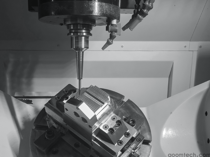
Holder choice also matters more in 5-axis than many new users expect. Haas recommends shrink-fit holders for speeds above 10,000 rpm and balanced tools for high-speed work. On complex surfaces, even a good toolpath can lose finish quality if the holder is not right for the spindle speed and overhang. Good balance and firm clamping become more important as the cutter tilts and the machine changes direction more often.
If chatter starts, do not only blame the program. Sandvik’s troubleshooting guide lists weak fixturing, excessive overhang, poor support, and chip re-cutting among common causes of vibration and poor surface finish. It also recommends minimizing overhang, improving support, adjusting cutting data, and improving chip evacuation with directed cutting fluid or compressed air. In other words, stable 5-axis cutting comes from the full system: machine, holder, tool, workholding, and toolpath.
Use the shortest tool and holder combination that still clears the part.
Separate roughing tools from finishing tools instead of forcing one cutter to do every step.
Choose stable holders and balanced assemblies for high speed work.
If the part has deep pockets or long chips, plan coolant or air for chip removal before you start the job.
Setup and workholding challenges
The hardest problems in 5-axis work often come from setup, not from cutting. Common setup challenges in 5 - axis CNC machining of complex parts include poor access, fixture collisions, not enough clearance during indexing, weak clamping, and a rotary that is too small or overloaded for the job. Haas advises users to define the workpiece size, match the platter size, and make sure the rotary can support the weight. It also recommends gripping as much of the blank as possible and positioning the part high enough off the table for clearance when indexing.
Accessibility is critical because 5-axis only helps if the spindle and holder can actually reach the work. SCHUNK’s 5-axis vise guidance highlights optimal accessibility and strong clamping for 5-axis applications, and its KSX vise description states that the design is intended to give access for true simultaneous 5-axis machining. This is why low-profile vises, dovetail clamping, custom jaws, or modular zero-point systems are common in multi-axis work. They open the part to the tool instead of blocking it.
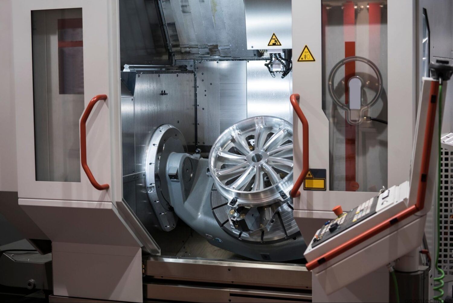
Machine configuration also affects setup decisions. Hurco notes that common 5-axis machine layouts include table-table, head-table, and head-head designs, and each has trade-offs. A trunnion can give strong undercut access and easy visualization for many users, while head-table or head-head designs can be better for heavier parts because the table does not have to tilt the full workpiece mass. Shops that handle both small intricate parts and large heavy parts should think about machine configuration early, not after the fixture is already designed.
One useful setup aid is control functions that reduce the need to place every fixture in exactly the same spot. Haas states that its DWO/TCPC feature lets users create the CAM program ahead of time and then place the workholding and part anywhere on the table without reposting the program. This is not a substitute for good setup practice, but it does reduce one common source of frustration in 5-axis prove-out.
Quality control and mistake prevention
Accuracy in 5-axis work depends on much more than spindle quality. Rotary axis positioning and the machine’s understanding of the center of rotation are critical. Haas explains that MRZP settings define the centers of rotation for the rotary axes relative to the machine home positions, and Renishaw states plainly that rotary axis positioning is critical to machine accuracy. If these values are wrong, the machine may follow the posted path but still miss the true feature location on the part.
That is why probing and calibration should be part of the process plan, not an afterthought. Haas says its probing system can define work offsets, set tool length offsets, and perform in-process inspection. In practical terms, that means you can verify setup, check features before the part leaves the machine, and catch tool breakage or drift before a full batch is lost. For complex and expensive workpieces, this is one of the most useful quality habits you can adopt.
Simulation is the other half of quality control. Autodesk emphasizes machine-specific simulation, collision avoidance, and visual verification on a digital twin before the job runs. This helps prevent over-travel, collisions, and bad rotary motion that may not be obvious from a simple backplot. On a complex 5-axis program, simulation is not only about avoiding a crash. It is also about checking that the machine can physically move the way the CAM system expects.
When surface finish looks poor, use a structured check. Sandvik lists vibration, chip re-cutting, excessive feed, spindle run-out, and poor clamping among the causes of bad milling finish. Haas adds that long overhang is a common reason for chatter and recommends reducing tool length, cut load, or both when long reach cannot be avoided. In many cases, the fix is not a new machine; it is better stability and a calmer process.
A simple shop-floor checklist before cycle start
If you want consistent results from 5-axis work, keep the process simple and repeatable. The most successful shops do not rely on guesswork. They use a short checklist every time a difficult job is loaded. That habit is more valuable than chasing every new CAM feature. The sources from Autodesk, Haas, Sandvik, Hurco, SCHUNK, and Renishaw all point in the same direction: good 5-axis results come from fewer setups, stable tools, accessible workholding, verified rotary geometry, and full simulation before the machine starts cutting.
Check whether the job really needs simultaneous 5-axis, or whether 3+2 will do the work faster and more safely.
Make sure the rotary size, weight capacity, and machine envelope fit the blank, holder, and fixture.
Use the shortest stable tool assembly possible, with the right holder for the spindle speed.
Build workholding for access first, not only for clamping force. The cutter must be able to reach the part through all planned angles.
Use collision avoidance, tilt limits, smoothing, and full machine simulation before posting and before prove-out.
Probe the setup, verify tool lengths, and inspect critical features in process when possible.
If finish or size drifts, check overhang, fixturing, chip evacuation, and cut stability before changing the whole program.
In the end, 5-axis machining is not only about owning a more advanced machine. It is about using that machine in a disciplined way. If you choose the right strategy, keep the tooling short and stable, build workholding for access, and verify motion before cutting, 5-axis becomes much less risky and much more profitable for complex parts.
 How to Ensure Precision in CNC
 Small Batch Precision CNC Mach
 What surface finish can CNC ma
 CNC Machining Tolerance Settin