
CNC Machining Tolerance Setting Standards
Introduction to CNC Machining Tolerance Setting Standards
CNC machining is widely used in modern manufacturing to produce high-precision parts. One of the most important concepts in this process is CNC Machining Tolerance Setting Standards. These standards define how much a finished part is allowed to differ from its original design dimensions while still being acceptable for use.
The Concept of CNC Machining Tolerance
Tolerance refers to the allowable variation between the designed size and the actual manufactured size of a part. In CNC machining, no part can be made with 100% exact precision, so small variations are always expected.
For example, if a shaft is designed to be 10.00 mm in diameter with a tolerance of ±0.02 mm, the real size can be between 9.98 mm and 10.02 mm. If the shaft is too large or too small, it may not fit into a bearing, causing assembly failure or poor machine performance.
Importance of CNC Machining Tolerance Setting Standards
Ensuring Part Functionality
The main goal of tolerance control is to ensure that parts work correctly in real applications. In mechanical assemblies, components must fit together with high accuracy.
For example, in an engine, piston rings require precise tolerances to maintain proper sealing. If tolerances are too loose, compression is lost, reducing engine efficiency and power output. If too tight, friction increases and may cause wear or failure.
This shows the clear importance of CNC machining tolerance standards in maintaining product performance and reliability.
Meeting Industry Requirements
Different industries have different tolerance expectations based on safety and performance needs.
Aerospace: Requires extremely tight tolerances due to high safety risks.
Automotive: Needs balanced tolerances for performance and cost efficiency.
Medical: Demands high precision for implants and surgical tools.
Cost-Effectiveness
Tighter tolerances require more advanced machines, better tools, and longer processing time, which increases cost. By selecting reasonable tolerances, manufacturers can reduce production costs while still meeting functional requirements.
This balance is a key part of efficient engineering and practical manufacturing decisions.
Common CNC Machining Tolerance Setting Standards
General Dimensional Tolerance Standards
General dimensional tolerances are often defined by international systems such as ISO standards like ISO 2768. These standards classify tolerances based on part size and required precision level.
For example, a drawing may specify a hole size of 20 mm ±0.05 mm. This means the acceptable range is from 19.95 mm to 20.05 mm.
Form and Position Tolerance Standards
Form and position tolerances are part of geometric dimensioning and tolerancing (GD&T), commonly defined through standards such as ASME Y14.5.
Form tolerances: Control shape (flatness, roundness, straightness).
Position tolerances: Control feature location (perpendicularity, concentricity).
For example, flatness tolerance ensures that two mating surfaces fully contact each other without gaps, improving assembly stability.
Surface Roughness Tolerance Standards
Surface roughness affects both performance and appearance. It is commonly measured using Ra (arithmetic average roughness).
Smooth surfaces are required for hydraulic systems to prevent leakage, while slightly rough surfaces may be acceptable for structural components.
Factors Affecting CNC Machining Tolerance Setting
Material Properties
Different materials behave differently during machining. Metals, plastics, and composites expand or deform under heat and cutting forces.
For example, aluminum expands more with heat, so slightly looser tolerances may be needed compared to stable materials like steel. Understanding factors influencing CNC machining tolerance setting helps engineers design more reliable parts.
Machining Processes
Different machining methods offer different precision levels:
Rough milling: Lower precision, used for initial shaping.
Finish milling: Medium precision for final shaping.
Grinding: Very high precision for tight tolerances.
Selecting the right process is essential to achieve the required accuracy efficiently.
Machine Capabilities
CNC machine accuracy depends on its mechanical quality, control system, and calibration condition. High-end machines can achieve extremely tight tolerances, while older machines may require looser limits.
Regular maintenance and calibration are essential to maintain stable precision.
Applying CNC Machining Tolerance Setting Standards in Practice
Design Stage
At the design stage, engineers must define tolerances based on function, cost, and manufacturability. Overly tight tolerances should be avoided unless necessary.
Good design practice includes using standard dimensions and avoiding unnecessary complexity. This is a key part of applying tolerance standards in CNC machining.
Manufacturing Stage
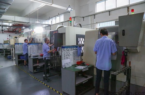
During manufacturing, machinists must follow specified tolerances by selecting proper tools, speeds, and cutting strategies. Real-time measurement tools help monitor part accuracy during production.
If deviations occur, adjustments such as tool offset correction or feed rate changes can help bring the part back within tolerance limits.
Quality Control Stage
Quality control ensures that finished parts meet required standards. Inspection tools such as calipers, micrometers, and coordinate measuring machines (CMM) are commonly used.
Non-conforming parts must be reworked or rejected to maintain product quality. Proper documentation of inspection results supports traceability and continuous improvement.
Conclusion
CNC Machining Tolerance Setting Standards play a critical role in ensuring product quality, performance, and cost control. By understanding how tolerances work and how they are applied across different industries, manufacturers can produce reliable and efficient components.
From design to production and final inspection, every stage depends on correct tolerance planning. Following international standards and considering material, process, and machine capability ensures consistent and high-quality results in modern CNC manufacturing.
 Process of Custom High-Precisi
 CNC Machining Parameter Settin
 5 Key Tips for CNC Machining o
 Small-batch Precision Parts 5-