
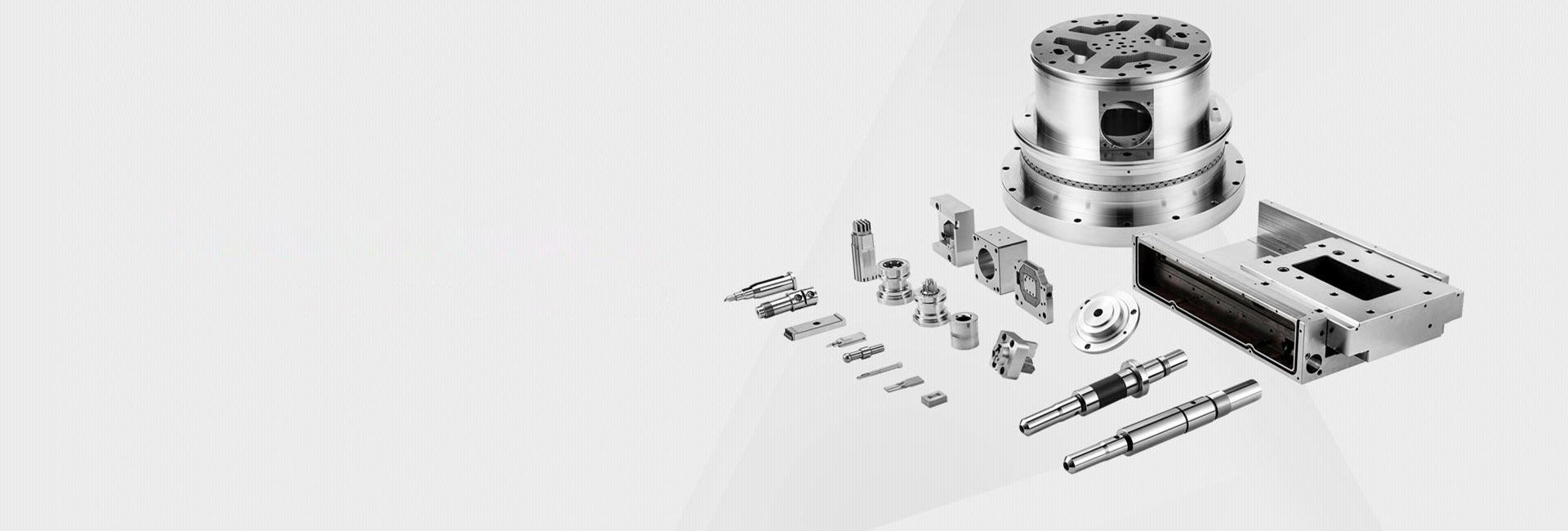

Guide to CNC Machining Process for Beryllium Copper Parts
The Guide to CNC Machining Process for Beryllium Copper Parts explains how manufacturers turn a high-performance alloy into precise, reliable components used in demanding industries. Beryllium copper is widely chosen for its excellent balance of strength, conductivity, corrosion resistance, and wear performance. However, machining this material requires careful planning, proper safety control, and optimized CNC processes to achieve high-quality results.
Introduction to CNC Machining of Beryllium Copper Parts
Properties and Applications of Beryllium Copper
Beryllium copper is a unique copper-based alloy with small amounts of beryllium added to improve mechanical strength while maintaining excellent electrical and thermal conductivity. It also offers strong corrosion resistance and good fatigue performance.
Because of these properties, it is widely used in industries such as:
Electronics – electrical connectors, switches, and relay components due to stable conductivity and spring performance.
Aerospace – precision springs, safety components, and structural connectors requiring high strength-to-weight performance.
Automotive – sensor parts, connectors, and transmission system components exposed to vibration and heat.
These applications require high accuracy and stable performance, which makes CNC machining the preferred manufacturing method.
Pre-Machining Considerations
Part Design and Engineering
Strong results in machining start with proper design. Engineers use CAD (Computer-Aided Design) software to develop a detailed 3D model of the part before production begins.
For successful pre-machining for beryllium copper CNC parts, designers should consider:
Avoiding sharp internal corners to reduce stress concentration
Adding smooth transitions between surfaces
Designing with proper wall thickness to prevent deformation
Ensuring tolerances are realistic for CNC capabilities
Good design reduces tool wear, prevents machining errors, and improves final part quality. Poor design, on the other hand, can lead to vibration, inaccurate cuts, or even tool breakage during machining.
Material Handling and Safety
Beryllium copper requires strict safety control during machining. While the solid material is relatively safe, dust and fumes generated during cutting can be hazardous if inhaled.
Safety guidelines include:
Using proper ventilation systems and dust extraction units
Wearing PPE such as masks, gloves, and protective clothing
Keeping machining areas clean to avoid dust accumulation
Following regulated handling procedures for beryllium-containing materials
Proper storage is also important. The material should be kept in a clean, dry environment to avoid contamination and maintain consistent machining performance.
Machine and Tool Selection
Selecting the right CNC machine and tools is essential for stable machining performance. Beryllium copper has moderate hardness, which requires strong and rigid machining systems.
Key considerations include:
CNC Machine: High rigidity machines with stable spindle systems are preferred
Spindle Speed: Medium to high-speed spindles help improve efficiency
Cutting Tools: Carbide end mills, drills, and inserts are recommended
Tool Coatings: Coated tools (such as TiAlN) help extend tool life
Tool selection should match the operation type, such as milling, turning, or drilling. Having backup tools available is also important to prevent downtime during production.
CNC Machining Operations
Rough-Machining Operations
Rough machining removes the majority of excess material quickly and prepares the part for finishing. In this stage, productivity is more important than surface quality.
In machining operations in beryllium copper part CNC process, rough machining typically includes:
Using large-diameter end mills for fast material removal
Applying higher feed rates and deeper cutting depths
Using strong coolant flow to reduce heat buildup
Optimizing toolpaths to reduce vibration and tool load
Proper rough machining reduces internal stress and creates a stable shape for finishing operations.
Finish-Machining Operations
Finish machining is the final stage that determines the accuracy and surface quality of the part. This process requires precision and stability.
Key practices include:
Using smaller, sharper cutting tools
Applying lower feed rates and shallow cuts
Using high-precision CNC control systems
Monitoring tool wear closely during operation
Finish machining ensures tight tolerances and smooth surface finishes, which are essential for high-performance applications like aerospace and electronics.
Specialized Machining for Features
Beryllium copper parts often include complex features such as internal threads, deep holes, and intricate cavities. These require specialized machining methods.
Tapping: Used for internal threads in connectors and assemblies
Deep Hole Drilling: Used for long and precise internal channels
EDM (Electrical Discharge Machining): Used for complex or hard-to-reach geometries
Each process requires precise programming and suitable tooling to ensure accuracy and prevent damage to the part.
Challenges in CNC Machining of Beryllium Copper Parts
Tool Wear
Beryllium copper can cause faster tool wear compared to softer materials. Continuous cutting increases friction and reduces tool life.
Solutions include:
Using carbide or coated tools for higher durability
Optimizing cutting speed and feed rate
Monitoring tool condition regularly
Replacing tools before failure occurs
Heat Generation
Heat is a common issue during machining and can affect dimensional accuracy and material properties.
To control heat:
Use high-quality coolant systems
Apply multi-pass cutting strategies
Avoid excessive cutting speeds
Allow cooling intervals when needed
Surface Finish
Achieving a smooth surface finish is essential for performance and durability. Poor machining can cause marks, burrs, or uneven surfaces.
Best practices include:
Using sharp cutting tools
Reducing vibration during machining
Optimizing spindle speed and feed rate
Applying post-processing polishing if required
Quality Control in Beryllium Copper CNC Machining
In-Process Inspection
Quality control in beryllium copper CNC machining starts during production. In-process inspection ensures that errors are detected early.
Common inspection methods include:
Measuring dimensions using calipers and micrometers
Checking surface roughness with specialized testers
Monitoring tool wear during machining
If deviations are found, adjustments can be made immediately, such as modifying toolpaths or replacing tools.
Final Inspection and Testing
After machining is complete, a full inspection ensures the part meets all requirements.
This includes:
Dimensional accuracy checks using CMM (Coordinate Measuring Machine)
Surface finish verification
Material property validation when required
Defective parts may be reworked or rejected depending on severity and application requirements.
Post-Machining Processes
Deburring and Edge Finishing
After machining, burrs and sharp edges must be removed to improve safety and performance.
Methods include:
Manual deburring using abrasive tools
Automated brushing systems
Electrochemical deburring for complex shapes
Edge finishing such as chamfering or rounding helps reduce stress concentration and improves durability.
Heat Treatment and Surface Treatment
Heat treatment can improve hardness, strength, and fatigue resistance. Surface treatments such as plating enhance corrosion resistance and improve appearance.
Common treatments include:
Aging heat treatment for strength improvement
Nickel or tin plating for corrosion protection
Protective coatings for wear resistance
The choice depends on the final application and performance requirements of the part.
Conclusion
The Guide to CNC Machining Process for Beryllium Copper Parts shows that successful manufacturing depends on careful planning, precise machining, strict safety control, and strong quality inspection. From design and material handling to final inspection and surface treatment, every stage plays an important role in ensuring performance and reliability.
By following optimized processes and understanding the challenges of this unique alloy, manufacturers can produce high-quality beryllium copper parts suitable for demanding industries such as aerospace, electronics, and automotive engineering.
 Process of Custom High-Precisi
 CNC Machining Parameter Settin
 5 Key Tips for CNC Machining o
 Small-batch Precision Parts 5-