
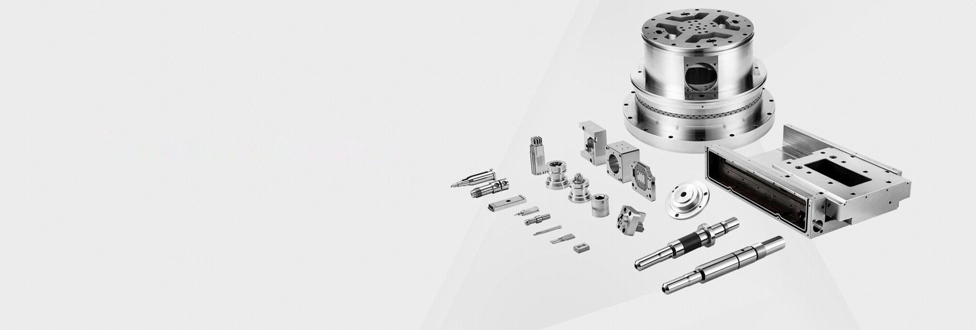
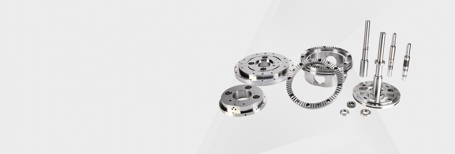
Process of CNC Machining Precision Metal Parts
The Process of CNC Machining Precision Metal Parts is a highly controlled and systematic workflow used to produce accurate, high-quality metal components for industries such as aerospace, automotive, medical devices, and industrial machinery. Every stage, from design to final inspection, plays a critical role in ensuring the finished part meets strict dimensional tolerances, surface finish requirements, and functional performance standards.
This article explains the complete step-by-step process in simple language so that engineers, buyers, and beginners can clearly understand how precision metal parts are manufactured using CNC technology.
Pre-machining Preparation
Part Design and Specification
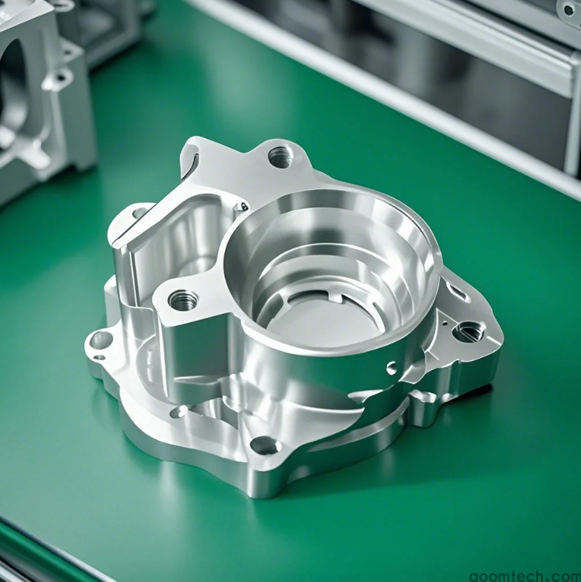
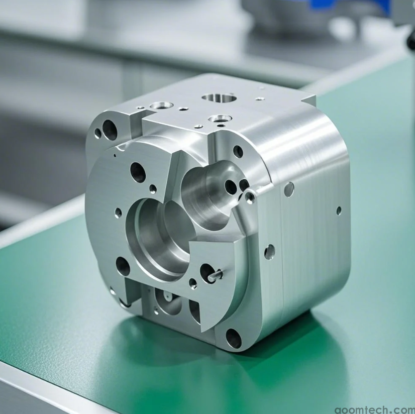
The process begins with detailed engineering design. Designers create a 3D model or technical drawing that defines every aspect of the part, including dimensions, tolerances, surface roughness, and functional requirements. This stage is often referred to as pre-machining for CNC machining precision metal parts.
A well-optimized design is essential for successful CNC production. Engineers must consider tool accessibility, machining direction, and fixture setup. For example, deep narrow cavities or sharp internal corners may increase machining difficulty or cause tool wear. Instead, designers often use fillets or rounded internal edges to improve manufacturability.
Practical tips for CAD (Computer-Aided Design) modeling include:
Using standard tolerances whenever possible to reduce machining cost
Avoiding unnecessarily complex geometries
Ensuring all critical dimensions are clearly defined
Designing with available CNC tools in mind (tool diameter, reach, and clearance)
A manufacturable design reduces production errors and improves efficiency in later stages of machining.
Material Selection
Choosing the right material is another key step in the Process of CNC Machining Precision Metal Parts. Different metals offer different mechanical and physical properties, which directly affect performance, machining speed, and cost.
Common materials include:
Aluminum – Lightweight, corrosion-resistant, and easy to machine; widely used in aerospace and electronics
Steel – High strength and durability; commonly used in automotive and industrial machinery
Titanium – Excellent strength-to-weight ratio and corrosion resistance; ideal for aerospace and medical implants
Copper and alloys – High electrical and thermal conductivity; used in electrical components
Material selection should be based on performance requirements, environmental conditions, and cost-effectiveness. For example, while titanium offers superior strength, it is more expensive and harder to machine compared to aluminum.
CNC Programming
Converting Design to Code
Once the design is finalized, it must be converted into machine-readable instructions using CAM (Computer-Aided Manufacturing) software. This step is known as CNC programming in precision metal part machining.
The CAM software generates toolpaths that guide cutting tools during machining. These toolpaths define how the machine removes material step by step.
Key machining parameters include:
Spindle speed (RPM)
Feed rate (tool movement speed)
Depth of cut
Tool selection and tool diameter
Different operations require different programming strategies:
Milling: Tool moves across a stationary workpiece to create complex shapes
Turning: Workpiece rotates while a stationary tool removes material
Drilling: Vertical tool movement creates holes
Accurate programming is essential because even small errors can lead to dimensional inaccuracy or tool damage.
Simulation and Verification
Before actual machining begins, the CNC program is tested using simulation software. This step helps visualize the entire machining process in a virtual environment.
Simulation helps detect issues such as:
Tool collisions with the workpiece or fixture
Incorrect toolpaths
Excessive cutting forces
Unnecessary tool movements that increase cycle time
By verifying the program in advance, manufacturers reduce the risk of machine damage, improve efficiency, and ensure higher precision in final production.
Machining Operations
Milling Operations
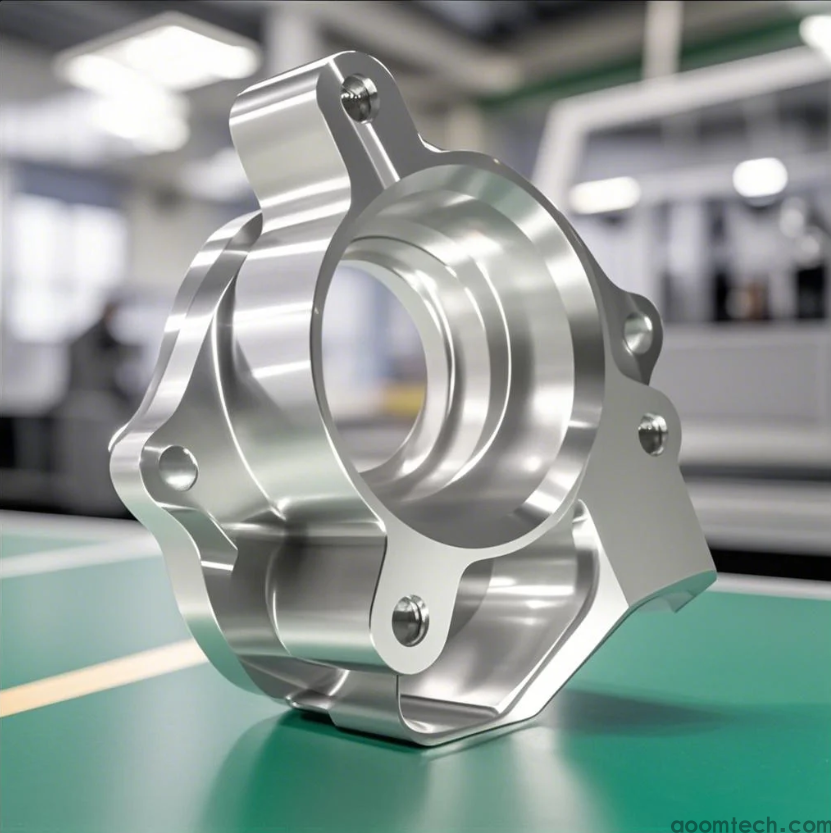
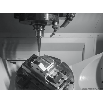
Milling is one of the most common operations in CNC machining. It uses rotating cutting tools to remove material from a fixed workpiece. Different tools are selected based on geometry and material type.
Common milling tools include:
End mills: Used for slots, pockets, and general contouring
Face mills: Used for large flat surfaces
Ball nose mills: Used for curved or 3D surfaces
Proper setup is essential for accuracy. This includes secure fixture clamping, correct tool alignment, and optimized cutting parameters based on material hardness. For harder metals like steel or titanium, slower feed rates and stronger cutting tools are required.
Turning Operations
Turning is used to produce cylindrical components such as shafts, bushings, and pins. In a CNC lathe, the workpiece rotates at high speed while the cutting tool shapes the outer or inner surface.
Common turning operations include rough turning and finish turning. Rough turning removes large amounts of material quickly, while finish turning achieves precise dimensions and smooth surface quality.
Important parameters include spindle speed, feed rate, and depth of cut. Carbide inserts are often used due to their durability and resistance to heat and wear.
Drilling and Boring
Drilling creates initial holes, while boring refines and enlarges them to achieve tight tolerances. These operations are essential in producing precision assemblies where accurate hole alignment is critical.
To improve accuracy and avoid common issues such as drill breakage or misalignment, manufacturers use:
Proper drill guides and fixtures
Correct cutting speeds based on material type
Coolant systems to reduce heat and friction
Step drilling for deeper holes
Boring tools are then used to achieve final dimensional accuracy and smooth internal surfaces.
Quality Control
In-process Inspection
Quality control is a critical part of the Process of CNC Machining Precision Metal Parts. In-process inspection ensures that errors are detected early before mass production continues.
Measurement tools commonly used include calipers, micrometers, and coordinate measuring machines (CMMs). These instruments check key dimensions such as diameter, flatness, and position accuracy.
Typical inspection points include:
Shaft diameter during turning operations
Flatness of milled surfaces
Hole position and depth accuracy
Early detection of errors helps reduce waste and improves production efficiency.
Final Inspection and Testing
After machining is completed, a final inspection ensures that the part fully meets design requirements. This includes dimensional measurement, surface roughness testing, and sometimes functional performance testing.
For example, a precision gear may be tested for smooth rotation and correct meshing with other gears. Any deviation from design specifications may require rework or rejection of the part.
Post-machining Operations
Deburring and Finishing
After machining, small sharp edges or burrs often remain on the part. These must be removed to ensure safety, functionality, and appearance. This step is known as deburring.
Common deburring methods include grinding, filing, tumbling, or chemical treatments. The choice depends on part complexity and material type.
Finishing processes may include:
Polishing: Improves surface smoothness and appearance
Plating: Enhances corrosion resistance and durability
Heat treatment: Improves hardness and mechanical strength
These finishing steps enhance both performance and product lifespan.
Conclusion
Understanding the Process of CNC Machining Precision Metal Parts is essential for engineers, buyers, and manufacturers who want to achieve high-quality and cost-effective production. From careful design and material selection to precise programming, machining, and strict quality control, every step contributes to the final accuracy and performance of the part.
By applying proper engineering practices and maintaining strong process control, manufacturers can consistently produce reliable precision metal components that meet demanding industrial standards.
 Process of Custom High-Precisi
 CNC Machining Parameter Settin
 5 Key Tips for CNC Machining o
 Small-batch Precision Parts 5-